Monday 30 October 2017

Customized Tab (Toolbar ) in SolidWorks


If you want to use your customized tab for fast and easy handling then you can make it very easily by follow some steps.

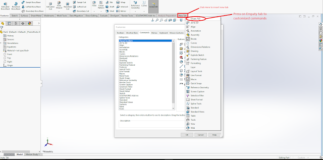
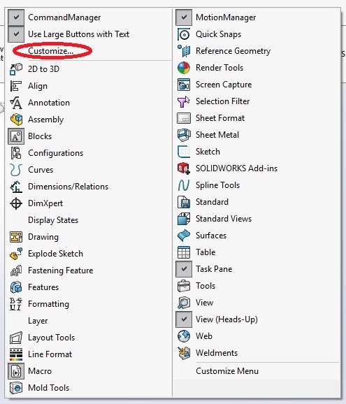
1- Go on option more tip and select "Customize....." . 
Or
 Right click near existing tab blank area. And select "Customize..."


2- Go on Commands tab. And also look after your existing tabs , you will get option for "New Tab" .

3- Click on "New Tab" -> "Empty Tab".


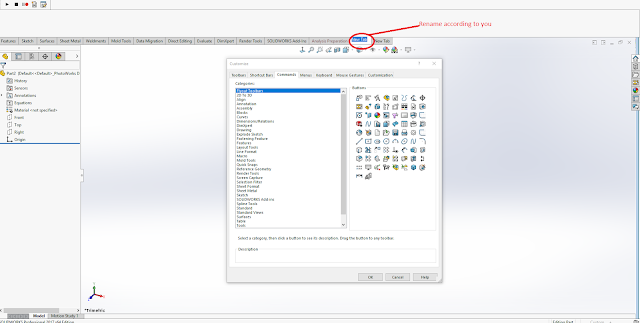
4- You can give a name for this Tab.
And by right click,you can delete , rename, hide tab, copy tab to assemble, copy tab to drawing and copy to tab to parts.


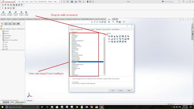
5- After renamed, you can add commands in this Tab by Drag from Right panel and choose command time (surface/feature/view/etc..) from Left panel.

Then press ok


Friday 27 October 2017

Add Macro Button (customize command) in SolidWorks .

You can add customised macro button to solidworks toolbar (and also generate new button in new toolbar) and that can linked by specific macro.


Steps- Follow steps to build button (customised command).


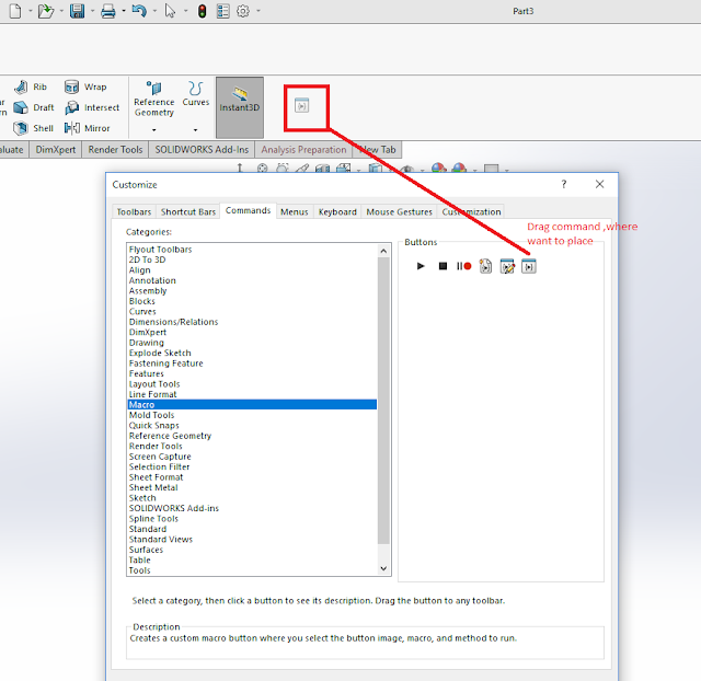
  1. Expand the option button and select customize.. Or Right click on free space near toolbar and select customize...


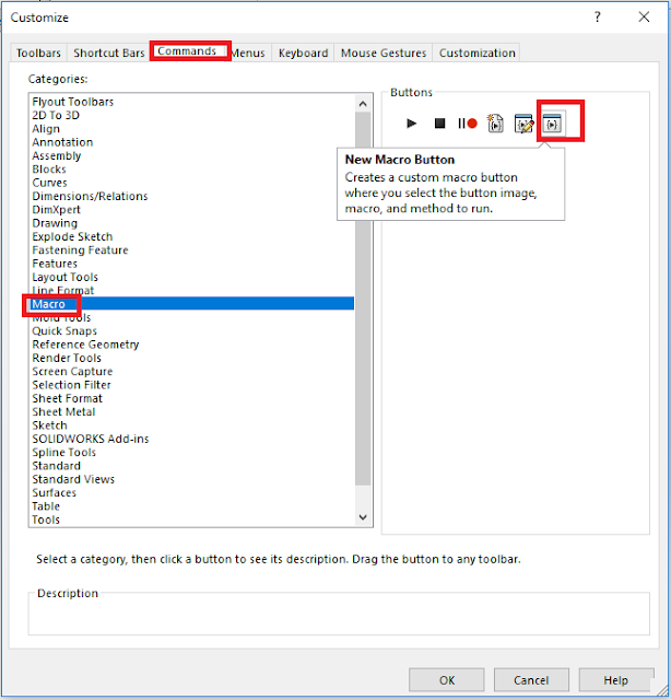
2. Go on Commands tab.
3. Select Macro in left hand panel.
4.  Select New Macro Button Command.


5. Drag command (new macro Button) where you want to place this new button (command).


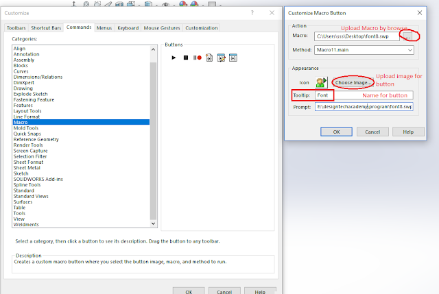
6. After placed, Customize Macro Button tab will open, where it will require some information, Ex-

  • Macro- Browse your macro file, which you saved in your system (computer/laptop).
  • Method- Program will start from. (by default)
  • Appearance - Image Icon, where you can select image for your button (command).
  • Tooltips- Name for button, which will display.
 
7. Press Ok. and also in Customize tab press Ok.


Wednesday 25 October 2017

Macro program to change font of dimension , note, section view text, and diameter / radius value in SolidWorks Macro.

This program/code will help to manage the all font in same size with one click in solidWorks drawing. you can make a command tool in drawing by this macro.
This program will cover-

  1.  Dimension font size
  2. Section view font size
  3. Diameter text location - horizontal
  4. Note font size
  5. Size of detail font size
  6. Save file after done all changes
In this program, font size is 8. you can change it as per requirement. 


Dim swApp As Object

Dim Part As Object
Dim boolstatus As Boolean
Dim longstatus As Long, longwarnings As Long

Sub main()

Set swApp = Application.SldWorks
Set Part = swApp.ActiveDoc

'dimension font size

Dim myTextFormat As Object
Set myTextFormat = Part.Extension.GetUserPreferenceTextFormat(swUserPreferenceTextFormat_e.swDetailingDimensionTextFormat, swUserPreferenceOption_e.swDetailingDimension)


myTextFormat.CharHeightInPts = 8
boolstatus = Part.Extension.SetUserPreferenceTextFormat(swUserPreferenceTextFormat_e.swDetailingDimensionTextFormat, swUserPreferenceOption_e.swDetailingDimension, myTextFormat)


'section font size

Dim myTextFormat1 As Object
Set myTextFormat1 = Part.Extension.GetUserPreferenceTextFormat(swUserPreferenceTextFormat_e.swDetailingSectionTextFormat, 0)
myTextFormat1.CharHeightInPts = 8
boolstatus = Part.Extension.SetUserPreferenceTextFormat(swUserPreferenceTextFormat_e.swDetailingSectionTextFormat, 0, myTextFormat1)
Set myTextFormat1 = Part.Extension.GetUserPreferenceTextFormat(swUserPreferenceTextFormat_e.swDetailingSectionLabelNameTextFormat, 0)
myTextFormat1.CharHeightInPts = 8
boolstatus = Part.Extension.SetUserPreferenceTextFormat(swUserPreferenceTextFormat_e.swDetailingSectionLabelNameTextFormat, 0, myTextFormat)
Set myTextFormat1 = Part.Extension.GetUserPreferenceTextFormat(swUserPreferenceTextFormat_e.swDetailingSectionLabelLabelTextFormat, 0)
myTextFormat1.CharHeightInPts = 8
boolstatus = Part.Extension.SetUserPreferenceTextFormat(swUserPreferenceTextFormat_e.swDetailingSectionLabelLabelTextFormat, 0, myTextFormat)
Set myTextFormat1 = Part.Extension.GetUserPreferenceTextFormat(swUserPreferenceTextFormat_e.swDetailingSectionLabelScaleTextFormat, 0)
myTextFormat1.CharHeightInPts = 8
boolstatus = Part.Extension.SetUserPreferenceTextFormat(swUserPreferenceTextFormat_e.swDetailingSectionLabelScaleTextFormat, 0, myTextFormat)
Set myTextFormat1 = Part.Extension.GetUserPreferenceTextFormat(swUserPreferenceTextFormat_e.swDetailingSectionLabelDelimiterTextFormat, 0)
myTextFormat1.CharHeightInPts = 8
boolstatus = Part.Extension.SetUserPreferenceTextFormat(swUserPreferenceTextFormat_e.swDetailingSectionLabelDelimiterTextFormat, 0, myTextFormat)
Set myTextFormat1 = Part.Extension.GetUserPreferenceTextFormat(swUserPreferenceTextFormat_e.swDetailingSectionView_RotationTextFormat, 0)
myTextFormat1.CharHeightInPts = 8
boolstatus = Part.Extension.SetUserPreferenceTextFormat(swUserPreferenceTextFormat_e.swDetailingSectionView_RotationTextFormat, 0, myTextFormat)


'diameter text location
boolstatus = Part.Extension.SetUserPreferenceInteger(swUserPreferenceIntegerValue_e.swDetailingDimensionTextAndLeaderStyle, swUserPreferenceOption_e.swDetailingDiameterDimension, swDisplayDimensionLeaderText_e.swBrokenLeaderHorizontalText)

boolstatus = Part.Extension.SetUserPreferenceInteger(swUserPreferenceIntegerValue_e.swDetailingDimensionTextAndLeaderStyle, swUserPreferenceOption_e.swDetailingRadiusDimension, swDisplayDimensionLeaderText_e.swBrokenLeaderHorizontalText)

'note font size


Dim myTextFormat2 As Object
Set myTextFormat2 = Part.Extension.GetUserPreferenceTextFormat(swUserPreferenceTextFormat_e.swDetailingNoteTextFormat, 0)
myTextFormat2.CharHeightInPts = 8
boolstatus = Part.Extension.SetUserPreferenceTextFormat(swUserPreferenceTextFormat_e.swDetailingNoteTextFormat, 0, myTextFormat2)

'SIZE OF DETAILS
Dim myTextFormat3 As Object
Set myTextFormat3 = Part.Extension.GetUserPreferenceTextFormat(swUserPreferenceTextFormat_e.swDetailingDetailTextFormat, 0)
myTextFormat3.CharHeightInPts = 8
boolstatus = Part.Extension.SetUserPreferenceTextFormat(swUserPreferenceTextFormat_e.swDetailingDetailTextFormat, 0, myTextFormat)

Dim myTextFormat4 As Object
Set myTextFormat4 = Part.Extension.GetUserPreferenceTextFormat(swUserPreferenceTextFormat_e.swDetailingDetailView_NameTextFormat, 0)
myTextFormat4.CharHeightInPts = 8
boolstatus = Part.Extension.SetUserPreferenceTextFormat(swUserPreferenceTextFormat_e.swDetailingDetailView_NameTextFormat, 0, myTextFormat)
Set myTextFormat4 = Part.Extension.GetUserPreferenceTextFormat(swUserPreferenceTextFormat_e.swDetailingDetailView_LabelTextFormat, 0)
myTextFormat4.CharHeightInPts = 8
boolstatus = Part.Extension.SetUserPreferenceTextFormat(swUserPreferenceTextFormat_e.swDetailingDetailView_LabelTextFormat, 0, myTextFormat)
Set myTextFormat4 = Part.Extension.GetUserPreferenceTextFormat(swUserPreferenceTextFormat_e.swDetailingDetailView_ScaleTextFormat, 0)
myTextFormat4.CharHeightInPts = 8
boolstatus = Part.Extension.SetUserPreferenceTextFormat(swUserPreferenceTextFormat_e.swDetailingDetailView_ScaleTextFormat, 0, myTextFormat)
Set myTextFormat4 = Part.Extension.GetUserPreferenceTextFormat(swUserPreferenceTextFormat_e.swDetailingDetailView_DelimiterTextFormat, 0)
myTextFormat4.CharHeightInPts = 8
boolstatus = Part.Extension.SetUserPreferenceTextFormat(swUserPreferenceTextFormat_e.swDetailingDetailView_DelimiterTextFormat, 0, myTextFormat)


'save file

Dim swErrors As Long
Dim swWarnings As Long
boolstatus = Part.Save3(1, swErrors, swWarnings)

End Sub


Download Macro- Click Here
Monday 23 October 2017

Add password on eDrawings in solidworks

If you want to protect your file of solidworks then you can only protect your eDrawings file.
When you save/saveas file as eDrawings.
Then

* Click file, password.
*Select password required option and input  password two time
Then ok

Sunday 22 October 2017

SolidWorks Short Introduction.

SolidWorks is a 3D CAD & CAE program which is developed by subsidiary of "Dassault Systemes" in USA.
SolidWorks initial version was on 1995 that was "SolidWorks 95", then it released in verious versions (SolidWorks 96, SolidWorks 97, SolidWorks 97 plus, SolidWorks 98, SolidWorks 99, SolidWorks 2000, SolidWorks 2001,SolidWorks 2001 plus, SolidWorks 2003,SolidWorks 2004, SolidWorks 2005, SolidWorks 2006, SolidWorks 2007, SolidWorks 2008, SolidWorks 2009, SolidWorks 2010, SolidWorks 2011, SolidWorks 2012, SolidWorks 2013, SolidWorks 2014, SolidWorks 2015, SolidWorks 2016, SolidWorks 2017, SolidWorks 2018 *till 2017).
It's Latest verion is 2018 which is released in Oct 2017.


System Requirements for SolidWorks-
For faster process and real graphics, it require Workstation and higher configuration but for Normal load we have to go with 8GB RAM (it require till 2017)


Some common Shortcuts which set default.
There Shortcuts can be changed by Settings as per requirement.


SolidWorks Interface is simple and easy to work where it have Menubar at the top which can be pin or not, stationary command area (command Manager) and Tool bar, At the right side it have Feature Manager Design Tree in which we can get used Equestion,senser and design history....ETC


Saturday 21 October 2017

Depth/Deep Symbol in GD&T

Depth/Deep


Depth/Deep  is used to indicate that a dimension applies to the depth of a feature and it is placed in front of the depth value in such
applications as for counterbore and hole.

  • Symbol size and details are in Pic.
  • h indicate font size if dimension.


EX-

Here is two dia shown in top view, one is dia .750 and second is dia 1,where first dia is throughout and second is counterbore which is only .625 deep.


Note- Tolerence also applied as per requirement or as per standard in depth.


Subscribe youtube channe for technical videos :-  Design Tech Academy

Visit for more technical notes and suppot. For plastic design :- Plastic Design For CATIA:- CATIA Tutorials For SolidWorks:- SolidWorks Tutorials For GD and T :- GD and T


Square symbol in GD&T

Square


Square Symbol is used to indicate that a single dimension applies to a square shape and the symbol precedes the dimension with no space between.The size of Square box used to indicate square have same height (h) and width(h) as font size used for dimension (h).

EX- The Square symbol applies to sqaure features as diameter symbol applies to cylinderical features.


Subscribe youtube channe for technical videos :-  Design Tech Academy

Visit for more technical notes and suppot. For plastic design :- Plastic Design For CATIA:- CATIA Tutorials For SolidWorks:- SolidWorks Tutorials For GD and T :- GD and T


Friday 20 October 2017

Short Introduction of CATIA

It's a short introduction of CATIA- "Computer aided three dimensional interactive application".


CATIA Released in verious versions- V1, V2, V3, V4,V5 (V5 released with its version value, ex- V5 R7) and V6.


System requirements- Below attached details for latest verions which require high process . May be it will require more then below details in future,where we will use more realistic views and past process.


Layout-Layout of CATIA is attached below, where we have differents areas and tool bar section for making our handling easy and faster.


Wednesday 18 October 2017

Difference between assemble and add Boolean operation in CATIA

Difference between assemble and add Boolean operation in CATIA

Add is the Boolean operation which is used to add the material no matter whether it is positive feature or negative feature but assemble is the one which considers if it is positive feature it adds material and if it is negative feature it removes material

Note: Positive feature are the options used to add material like pad, shaft, rib, multi section solid..... etc
negative feature are the options used to removes material like pocket, groove, slot, remove multi section solid.....etc

EX-
Here we have two bodies from which Body 1 is positive feature (Pad) & section is Negativve feature (Pocket) based.


When we use Assemble option in Boolean, then we can observe that body 2 removed comman material from body 1 and form a single body (body1)


When we use Add Option from Boolean then it will form a single body (merge bodies)


NOTE- Assembly and add command defference can observed by using opposite feature used at same time otherwise both generate same result (merged bodies).

Video Tutorial:-


Some More Video Tutorial...


Section view/Cut (Dynamic Sectioning) in CATIA

Dynamic Sectioning allows you to visualize a section of a part at a specified position.
In Below attached pic-1,you can see tool for dynamic sectioning.

Dynamic sectioning is used for view different section and internal details in 3D Part Model.

*In this example, A socket is placed for which we have to check internal view or section view with respect to any plane or any face.

Step1- Select command "Dynamic Sectioning"
                                                                          Pic-1
Step2- Select the Plane/Face for reference to generate view. (Ex-YZ plane Selected)
            For translation and rotation- there are 3 direction for translation and 3 rotational indicator to rotate Section view plane. (Red color plane in pic- 2)


Pic-2

To Leave command- Press "ESC" Key, Select again command "Dynamic Sectioning.

Tuesday 17 October 2017

CATIA interview Questions and Answer


Q1- What do you know about CATIA?
Ans- CATIA- Computer Aided three dimensional Interactive Application.
  • Catia is great for generative shape design and has a really advanced surface modeling module.
  • CATIA is product life cycle management software which has all required Tool like CAD, CAM, CAE, ergonomics analysis, more advance CFD, etc
  • CATIA used for bigger and huge projects like e.g aerospace,automobile design and development

Q2- Part file extension?

Ans- .CATPART.

Q3- Drawing file extension?

Ans- CATDRAWING

Q4- Kernel of CATIA?
Ans- CNEXT

Q5- STEP File meaning?
Ans-  Standard for the exchange of products.

Q6 - what are default unit of length, Time and mass?
Ans - Length- mm
           Mass- Kg
          Time- second

Q7 - what is thickness of surfaces?
Ans- infinity less.

Q8 - what is hybrid modeling ?
Ans- mixture of solid and surface modeling.

Q9 - How many degree of freedom in assembly?
Ans- 6

Q10 - How many degree of freedom for point in sketch?
Ans- 2

Q11 - Can we use non- planer surfaces for sketch?
Ans- No

Q12- what is the full form of IGES?
Ans- Initial graphics exchange  specification.

Q13 - How we can use any command more then one time (continue) in Catia?

Ans- By selecting double click we can use any command (tool) more then one time.

Q14- Difference b/w geometrical and dimensional constraints?
Ans- Geometric constraint is a relationship that forces a limitation b/w one or more geometric elements.
Dimensional constraint is a constraint, whose value determines the geometric object measurement.

Q15- Expamd CAM/CAD/CAE/PLM/VPM/VPDM/CFD.
Ans- CAM- Computer aided Manufacturing
         CAD- Computer aided Designing
         CAE- Computer aided Engineering
        PLM- Product life cycle management
        VPDM-  Virtual product data management
         VPM-  Virtual product module
         CFD- Computational fluid dynamic.

Q16- What is difference between add and assembly in catia v5?
Ans-  Add is the Boolean operation which is used to add the material no matter whether it is positive feature or negative feature but assembly is the one which considers if it is positive feature it adds material and if it is negative feature it removes material

Note: Positive feature are the options used to add material like pad, shaft, rib, multi section solid..... etc
negative feature are the options used to removes material like pocket, groove, slot, remove multi section solid.....etc

Add & Assembly DifferenceClick Here

Q17- Save extension of assembly file?
Ans- .CATProduct

Q18- What do CATIA P1, CATIA P2, and CATIA P3 means?
Ans- P1,P2 and P3 will indicate the different types of platforms of CATIA, Higher the number, Sophisticated will be the software.

Sunday 8 October 2017

Geometric Dimensioning and Tolerancing (GD&T)


GD&T-
  • GD&T is a symbolic language for defining and communicating engineering tolereances.
  • Used to specify the size, shape, form, orientation, and location of features on a part.
  • GD&T was created to insure the proper assembly of mating parts, to improve quality, and to reduce cost.
  • Drawings with properly applied geometric tolerancing provide the best opportunity for uniform interpretation and cost-effective assembly.

History-
DuringWorldWar II, the United States manufactured and shipped spare parts, Many of these parts were made to specifications but would not assemble.They recognized that producing parts that do not properly fit or function is a serious problem since lives depend on equipment that functions properly. To find a way to insure that parts would properly fit and function every time. The result was the development of GD&T.
GD&T has been credited to a man named "Stanley Parker", who developed the concept of "true position".
Ultimately, the USASI Y14.5–1966 document was produced on the basis of earlier standards and industry practices. The following are revisions to the standard:
ANSI Y14.5–1973 (American National Standards Institute)
ANSI Y14.5M–1982
ASME Y14.5M–1994 (American Society of Mechanical Engineers)
The 1994 revision is the current, authoritative reference document that specifies the proper application of GD&T.

Three important advantages over the coordinate tolerancing system:

  • The cylindrical tolerance zone
  • The maximum material condition
  • Datums specified in order of precedence


Subscribe youtube channe for technical videos :-  Design Tech Academy

Visit for more technical notes and suppot. For plastic design :- Plastic Design For CATIA:- CATIA Tutorials For SolidWorks:- SolidWorks Tutorials For GD and T :- GD and T


Thursday 5 October 2017

Solution 1- active REALVIEW GRAPHICS in solidworks 2016/17


1.Open the registry (Run -> regedit)
2.Go at -"HKEY_CURRENT_USER>SOFTWARE>Solidworks>SOLIDWORKS 2015>Performance>Graphics>Hardware>Current"
3. Double click on the "Renderer" key and copy the text under "Value Data". For example, for the GTX 770 mine was "GeForce GTX 770/PCIe/SSE2"
4.Go at -"HKEY_CURRENT_USERSOFTWARE>Solidworks>SOLIDWORKS 2016>Performance>Graphics>Gl2Shaders>NV40" 
* In solidworks folder, there will be that software+version name which is installed in system"
Ex-
"HKEY_CURRENT_USERSOFTWARE>Solidworks>SOLIDWORKS 2015>Performance>Graphics>Gl2Shaders>NV40" 
Or
"HKEY_CURRENT_USERSOFTWARE>Solidworks>SOLIDWORKS 2017>Performance>Graphics>Gl2Shaders>NV40"
5.Right-click on the NV40 folder on the left pane and select "New -> Key"
6.Rename the new key with what was copied in step #3
7.The only key in this folder should be a "(Default)" key
8.Right-click on the right pane and select "New -> DWORD (32-bit) Value"
9.Name this new key "Workarounds"
10.Double-click on the "Workarounds" key and enter the value "30408". You should be in Hexadecimal mode.
11.RealView should now be available. If it is not, try setting the value in step #10 to "31408" or "30008".

Sunday 1 October 2017

(3) GD&T Symbols - Diameter, Radius, Controlled Radius and Spherical Radius/Dia

  • Diameter (ø) -
    Indicates a circular feature when used on the field of a drawing or indicates that tolerance is  diametrial when used in a feature control frame.

                   OR
     Diameter symbol replaces the word "Diameter". It should be used anywhere there is a diameter on the drawing,abd when a tolerence zone is cylindrical.

    Ex-


  • Radius (R)-   A straight line extending from the center of an arc or circle to its surface.


    EX-


Controlled Radius (CR)-  Creates a tolerance zone defined by two arcs (the minimum and maximum radii) that are tangent to the adjacent surfaces. Where a controlled radius is specified, the part contour within the crescent-shaped tolerance zone must be a fair curve without flats or reversals. Additionally, radii taken at all points on the part contour shall neither be smaller than the specified minimum limit nor larger than the maximum limit.
The Abbreviation
CR is defined by 1994 standard to indicate a controlled radius dimension.


  • Spherical Radius (SR) Or Spherical Diameter (Sø)
    Spherical Diameter - shall precede the tolerance value where the specified tolerance value represents spherical zone. Also, a positional tolerance may be used to control the location of a spherical feature relative to other features of a part. The symbol for spherical diameter precedes the size dimension of the feature and the positional tolerance value, to indicate a spherical tolerance zone.

    SR
    Spherical Radius - precedes the value of a dimension or tolerance.

                                 OR
    Spherical Features may be dimensioned by giving either the radius of diameter of a sphere.


    Ex
    -


Subscribe youtube channe for technical videos :-  Design Tech Academy

Visit for more technical notes and suppot. For plastic design :- Plastic Design For CATIA:- CATIA Tutorials For SolidWorks:- SolidWorks Tutorials For GD and T :- GD and T


Some video Tutorials:-
                                  

Ads