Wednesday, 22 January 2025

Difference in sliders and lifters for plastic parts

Sliders and lifters are key components in injection molding tools used to form complex plastic parts. While both are used to release undercuts and complex geometries, they differ in function, design, and application. Here’s a detailed comparison:

---

1. Function

Sliders:

Used to create external undercuts or side features such as holes, slots, or threads.

Slides laterally (perpendicular to the mold opening direction) to clear the undercut before the mold opens.

Lifters:

Used to form internal undercuts or features inside the part.

Moves at an angle to lift or push the part away from the undercut as the mold opens.

---

2. Motion

Sliders:

Moves in a straight, lateral motion.

Driven by cam pins or hydraulic mechanisms.

Lifters:

Moves in a combined angular and linear motion.

Tilts or pivots as it pushes the part out of the mold.

---

3. Design

Sliders:

Consist of a sliding block that is guided by a cam pin or rail.

Requires space in the mold for lateral movement.

Lifters:

Feature a lifting pin or bar with an angled head.

Typically require less space compared to sliders.

---

4. Applications

Sliders:

Suitable for external features like:

Side holes.

Side slots.

Side protrusions or ribs.


Lifters:

Suitable for internal features like:

Undercut cavities.

Snap-fit hooks.

Internal ribs or threads.


---

5. Complexity

Sliders:

More complex to design and manufacture due to the need for precise lateral movement.

Increases mold size and cost.

Lifters:

Simpler compared to sliders but can be challenging to design for angled and precise movements.

Generally smaller and cost-effective.

---

6. Maintenance

Sliders:

Requires regular maintenance due to wear on sliding surfaces.

Higher risk of misalignment over time.

Lifters:

Easier to maintain as they have fewer moving parts.

Lower wear compared to sliders.

---

7. Cost

Sliders:

More expensive due to complex mechanisms and space requirements.

Lifters:

Less expensive as they are simpler in construction.

---

Summary Table

---

Both sliders and lifters are essential for creating detailed plastic parts with undercuts, and their selection depends on the specific design and geometry of the part.

Tuesday, 21 January 2025

Managing Large Assemblies in CATIA 3D: Tips and Best Practices

Managing Large Assemblies in CATIA 3D: Tips and Best Practices

Working with large assemblies in CATIA 3D can be both exciting and challenging. These complex models demand not just design expertise but also effective system and software management to ensure smooth performance. Without proper optimization, handling large assemblies can lead to slow performance, crashes, and wasted time. In this blog, we’ll explore practical tips and techniques to efficiently manage large assemblies in CATIA 3D.


---

Understanding the Challenge of Large Assemblies

Large assemblies often consist of thousands of components, detailed geometries, and multiple sub-assemblies. This complexity can overwhelm your system's hardware and CATIA's processing capabilities. However, with the right strategies, you can minimize lag and optimize your workflow.


---

1. Optimize Your Hardware for Better Performance

To handle large assemblies effectively, start by ensuring your hardware meets the demands:

Upgrade Your System: Use a computer with high RAM (32GB or more), a dedicated graphics card, and SSD storage.

Enable 64-bit CATIA: The 64-bit version of CATIA utilizes more memory, reducing limitations of the 32-bit version.

Keep Drivers Updated: Ensure your graphics and system drivers are up-to-date for compatibility and performance.


---

2. Adjust CATIA Settings for Efficiency

CATIA offers multiple performance-enhancing options that can significantly improve handling of large assemblies:

Lower Display Quality:

Go to Tools > Options > General > Display and reduce the "Shading Level of Detail."

Enable "Simplified Representation" to show basic shapes instead of detailed models.


Enable Memory Management:

Use Tools > Options > General > Memory Management to limit the number of parts loaded into memory.


Activate Culling: Display only visible components to reduce system load.


---

3. Use Lightweight Components

Loading large assemblies in full detail isn’t always necessary. CATIA provides lightweight visualization options:

CGR Files: Save parts as CGR (Catia Graphical Representation) files, which display only the graphical representation of components, reducing file size and loading time.

Visualization Mode: Open assemblies in “Visualization Mode” to view the structure without loading full part details.


---

4. Simplify Geometry and Representations

Simplification reduces the complexity of individual parts while maintaining functionality:

Defeature Parts: Remove unnecessary details like fillets, holes, or small features.

Use Substitutes: Replace detailed components with simple shapes (e.g., cubes or cylinders).

Simplified Assemblies: Use simplified versions of sub-assemblies to reduce computational load.


---

5. Divide and Conquer

Managing large assemblies is easier when broken down into smaller sections:

Sub-Assemblies: Divide the assembly into logical sub-assemblies and work on them individually.

Sections and Clipping: Use section views or clipping planes to isolate and focus on specific areas.


---

6. Suppress or Hide Unused Components

Loading all components of an assembly at once isn’t always necessary:

Suppress Components: Temporarily disable parts that are not required.

Hide/Show Parts: Use the Hide/Show feature to reduce on-screen clutter.


---

7. Use Advanced Tools and Techniques

Leverage CATIA’s built-in tools for large assembly management:

Cache System: Enable the CATIA cache to load lightweight representations instead of full models.

Batch Processing: Use batch tools to automate tasks like model cleanup or updating assemblies.

Search Tool: Quickly locate and isolate specific components in a large assembly.


---

8. Collaborate Effectively

For team projects involving large assemblies:

Divide Work: Assign specific sub-assemblies or sections to team members.

Use PLM Tools: Tools like ENOVIA streamline collaboration by managing versions, revisions, and large data sets.


---

Conclusion

Managing large assemblies in CATIA 3D requires a combination of hardware optimization, software settings, and smart design practices. By simplifying geometry, utilizing lightweight representations, and dividing your assembly into manageable sections, you can significantly improve performance and workflow efficiency.

With these strategies, you’ll not only handle large assemblies better but also save time and reduce frustration. So, the next time you work on a massive project in CATIA, remember these tips and take control of your design process!


---

Did you find these tips helpful? Share your thoughts or experiences with handling large assemblies in the comments below!


Monday, 20 January 2025

What is shut off angle and it's used in plastic parts?

What is Shut-Off Angle?

A shut-off angle in plastic part design refers to the angle between two mold surfaces that come together to block or "shut off" the flow of molten plastic during the injection molding process. These surfaces meet without leaving any gaps, ensuring no plastic leaks into unintended areas.

Shut-off angles are typically used in features such as holes, undercuts, or areas where two mold halves must create a seal without the use of additional components like slides or lifters.

---

Uses of Shut-Off Angle in Plastic Parts:

1. Sealing Two Mold Surfaces:

The shut-off angle ensures that the two mold surfaces come together tightly to prevent molten plastic from seeping into undesired areas.

2. Creating Undercuts or Side Features:

Shut-off angles allow for the formation of sidewalls, undercuts, or openings without requiring complex mold mechanisms.

3. Minimizing Flash:

Proper shut-off angles help eliminate or reduce flash (excess plastic) around parting lines, resulting in a cleaner final part.

4. Simplifying Mold Design:

By designing with effective shut-off angles, the need for secondary operations like machining or trimming is minimized, reducing production complexity and cost.

5. Improving Mold Life:

Correct shut-off angles reduce wear on the mold, as there’s a clean seal between surfaces, avoiding unnecessary stress or deformation during ejection.

---

Typical Shut-Off Angle Values:

A shut-off angle is typically 3° to 5° to ensure proper sealing and easy part ejection. Smaller angles may lead to poor sealing, while larger angles may not be practical for tight design tolerances.

---

Example Applications:

1. Snap-Fit Features:

Shut-off angles are used to create interlocking features in plastic parts like snap-fits.

2. Holes or Slots:

When forming holes or openings in the side walls of a part, shut-off angles allow the mold halves to meet precisely and seal.

In summary, shut-off angles are crucial for ensuring the quality and precision of plastic parts while optimizing mold functionality.

Sunday, 19 January 2025

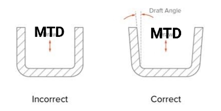
Why drafts is required on plastic parts and it's minimum values.

Drafts are essential on plastic parts to ensure they can be easily removed from the mold during the injection molding process. Here's why drafts are required and why they should have minimum values:


Reasons for Drafts:

1. Easier Mold Release:

During injection molding, the plastic part cools and shrinks slightly, which can cause it to stick to the mold surfaces. A draft angle (a slight taper) allows the part to be released without damaging the part or the mold.

2. Prevents Part Damage:

Without a draft, the part may experience scratches, warping, or deformation during ejection from the mold.

3. Reduces Ejection Force:

A draft reduces the friction between the part and the mold, requiring less force to eject the part.

4. Improves Surface Finish:

Proper drafts ensure the part comes out smoothly, avoiding drag marks or defects on the surface.

5. Extends Mold Life:

By reducing the wear and tear during ejection, drafts help extend the mold's lifespan.

---

Why Minimum Draft Values?

1. Dimensional Accuracy:

Excessive draft angles can alter the intended dimensions of the part, especially in areas where precision is critical.

2. Aesthetic Requirements:

Overly large drafts might affect the design or appearance of the part, leading to customer dissatisfaction.

3. Functional Fit:

Parts with excessive drafts might not fit well with other components in assemblies.

4. Material Properties:

Some plastics shrink more than others. A minimum draft angle should consider the material's shrinkage rate to balance ease of ejection with the part's integrity.

---

Typical Minimum Draft Angles:

General rule: 0.5° to 2° is sufficient for most plastic parts.

Texture considerations: For textured surfaces, drafts of 3° or more may be required to prevent sticking.

By designing with the correct minimum draft angle, manufacturers can ensure efficient production, maintain quality, and reduce costs.